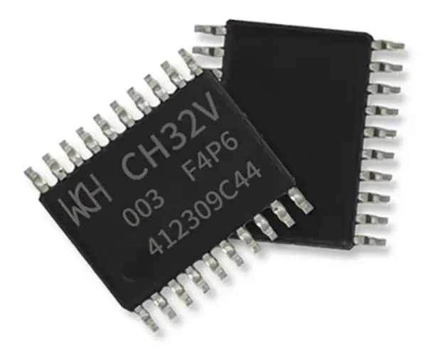
The Tiny Scarab is an open-source development board (Check out the GitHub page) built around the popular 10 cent CH32V003F4P6 RISC-V microcontroller from WCH.
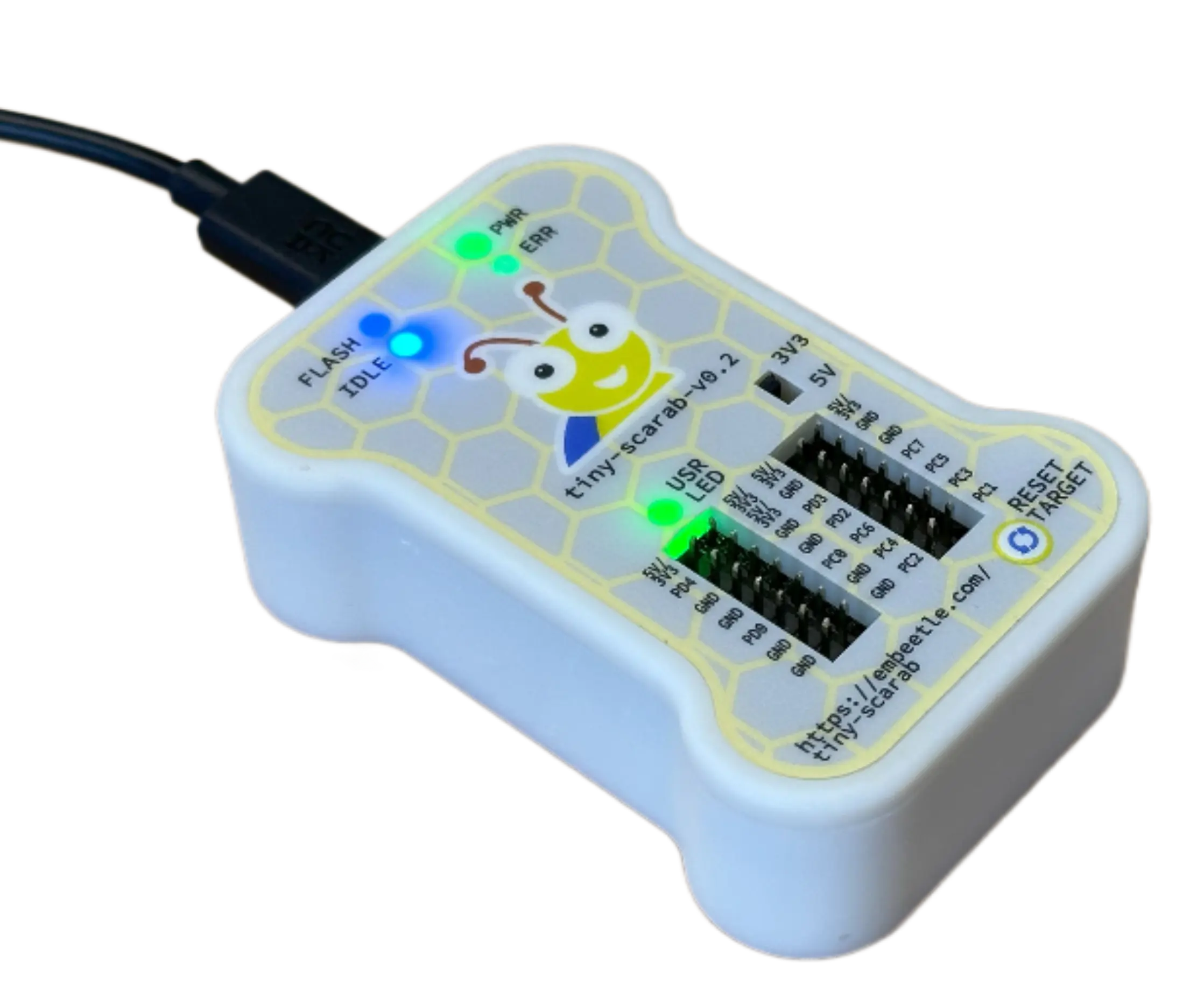
This dev board is easy to use: connect it to your computer, fire up Embeetle IDE and start coding. The board has a build-in flash/debug probe, so you don't need to wire up anything. Besides, it comes in a sturdy 3D printed case:
Great news: you can now purchase our Beetle Board on Elecrow!
![]() Click
here to purchase.
Click
here to purchase.
Now you might wonder - why yet another dev board? Aren't there thousands already? Well -
this dev board is presented to you with ![]() Embeetle
IDE:
Embeetle
IDE:
It's the perfect device to show the power of our microcontroller IDE. Discover how smooth programming a microcontroller can be!
The Tiny Scarab board is based on the 10-cent RISC-V CH32V003F4P6 MCU from WCH:
We merged the WCH-LinkE-R0-1v3 flash/debug probe and the CH32V003F4P6-EVT-R0-1v1 into a single development board:
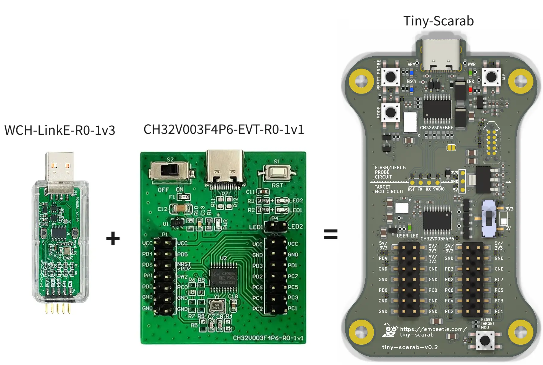
There's no need to wire up anything. Just plug the Tiny Scarab's USB-C port in your computer, fire up Embeetle IDE and start coding!
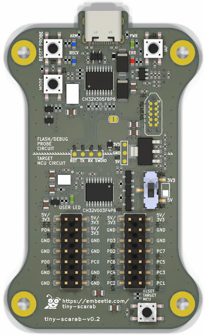
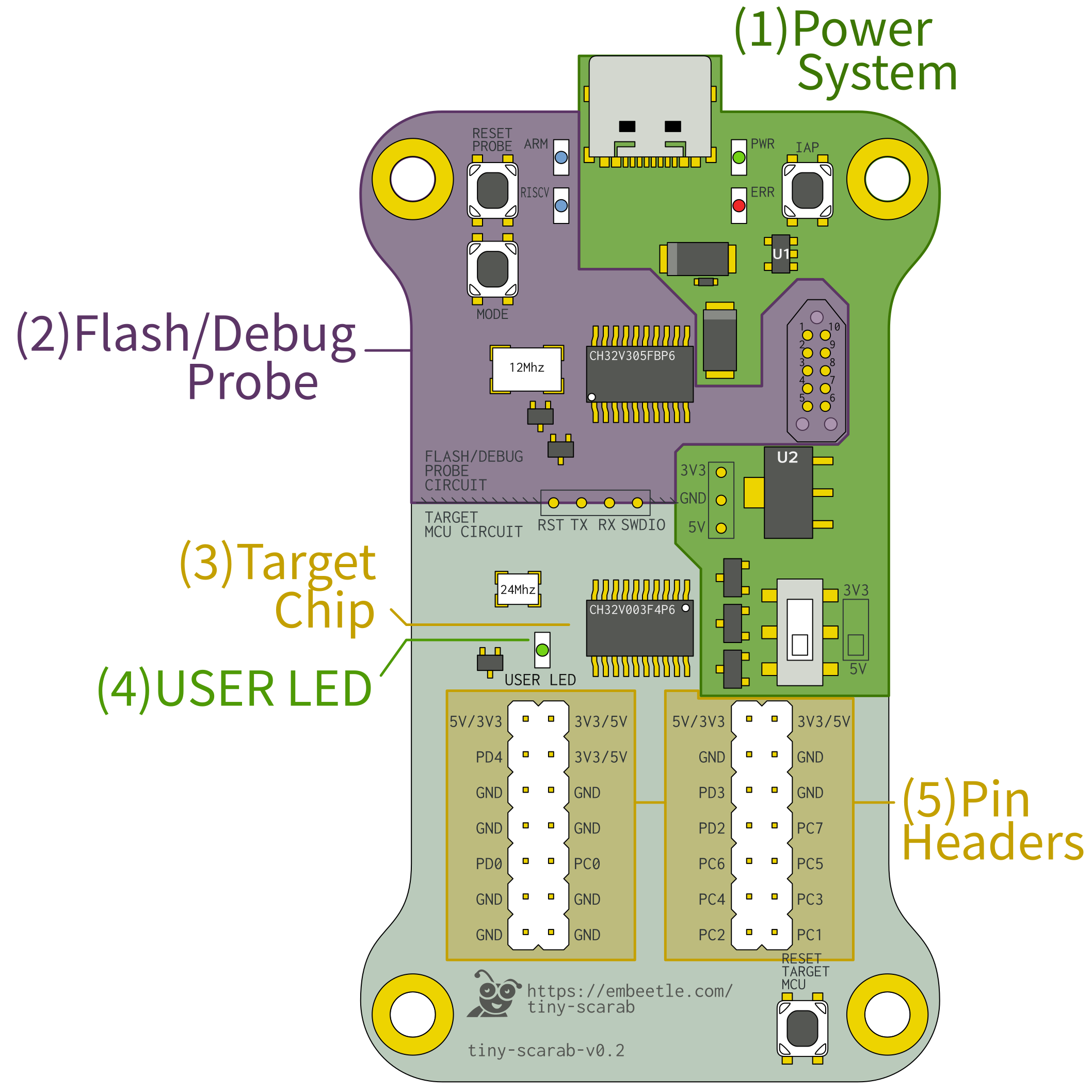
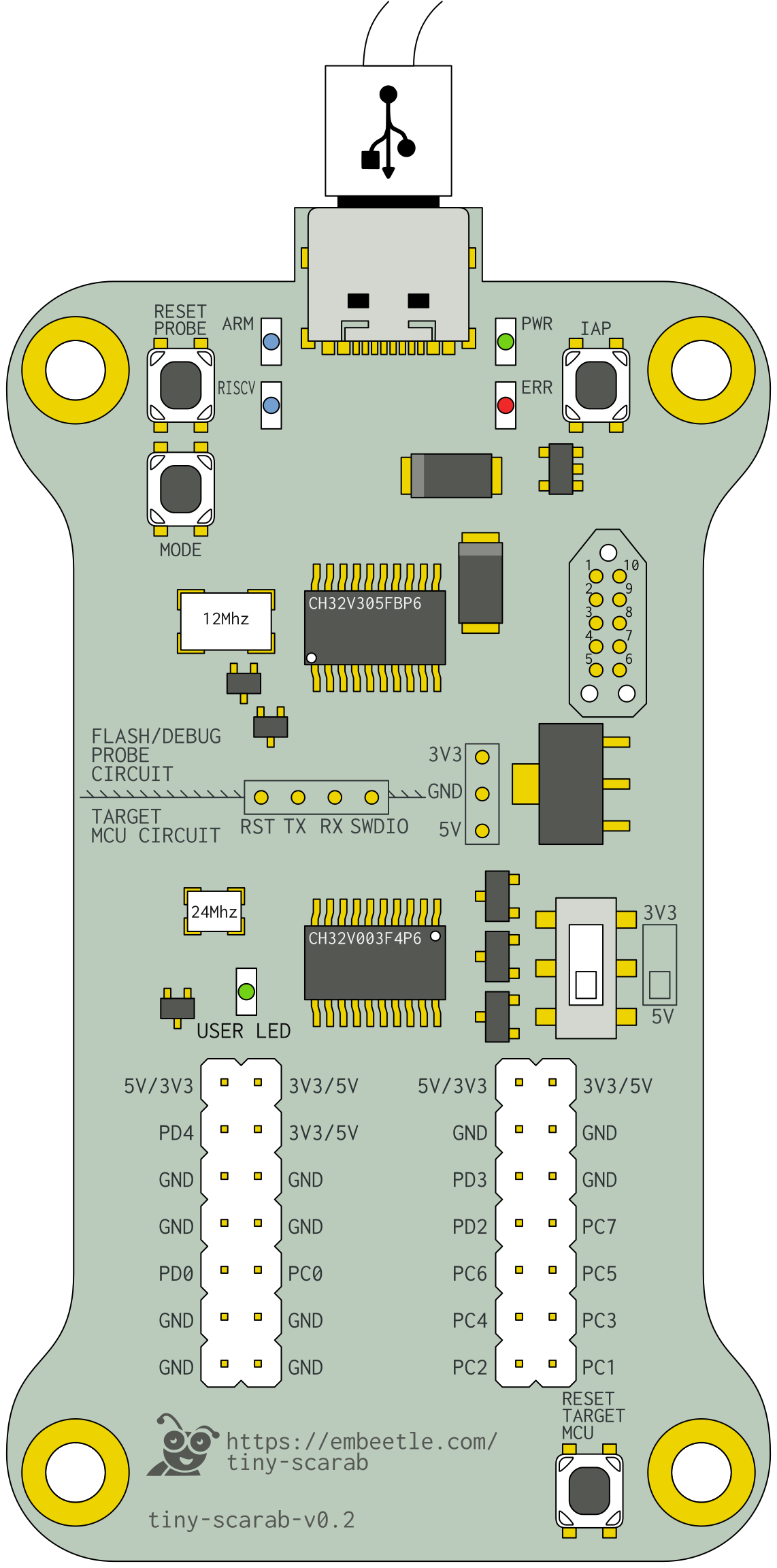
The Tiny Scarab board consists of two parts: the FLASH/DEBUG PROBE CIRCUIT (aka on-board probe) and the TARGET MCU CIRCUIT:
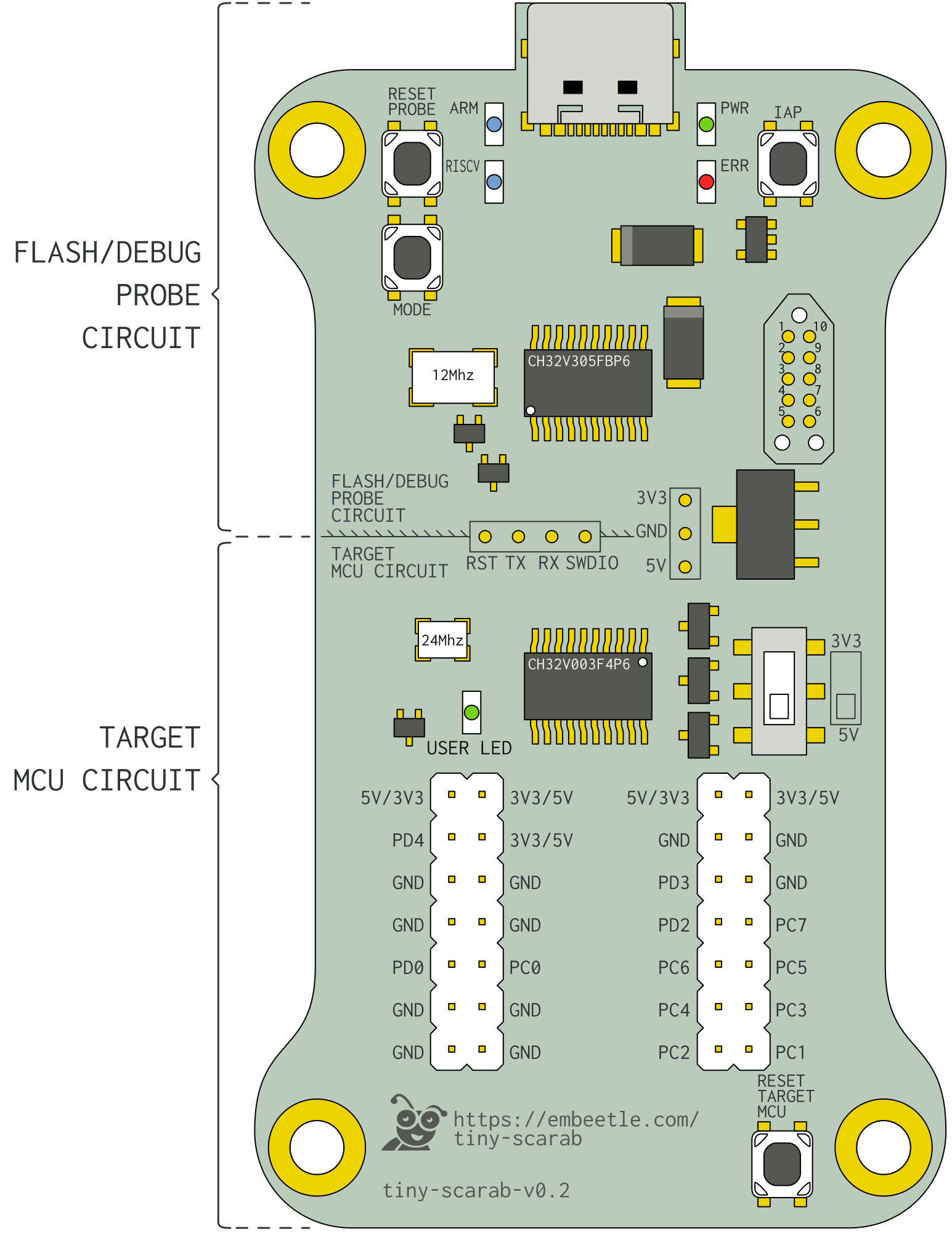
The USB-C connector at the top provides power to the entire board.
All pins of the CH32V003F4P6 target MCU are accessible through the pin headers left and right. One of them is also connected to the 'USER LED' next to the target MCU:
Some of the CH32V003F4P6 are not accessible on the pin headers, because they're used for the communication with the flash/debug probe. These pins are accessible on the test pads in the middle of the board.
Below is an overview of the components on the board:
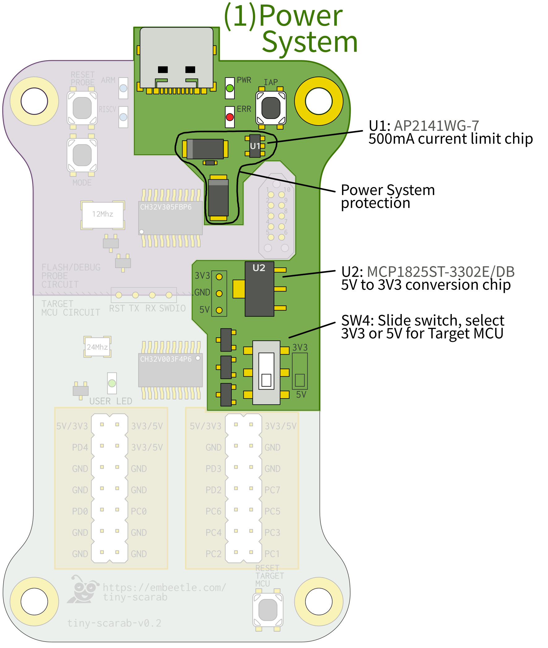
The USB-C connector provides power to the whole board. Chip U2 converts the incoming 5V to 3V3. That's because the upper part of the board - the flash/debug probe - operates entirely on 3V3. The lower part of the board - the target MCU circuitry - can operate on either 3V3 or 5V. The slide switch lets you choose between both modes:
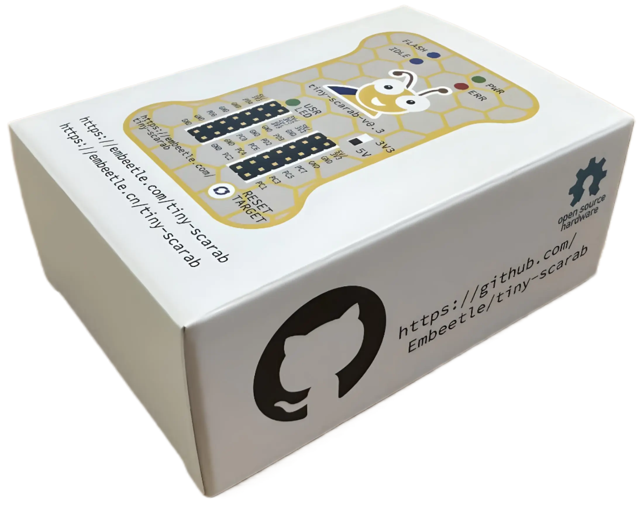
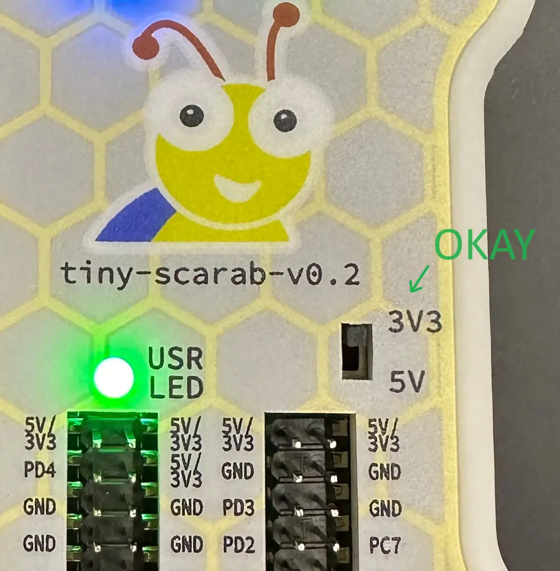
ATTENTION: The silkscreen indication on the tiny-scarab-v0.1 and tiny-scarab-v0.2 boards is incorrect:
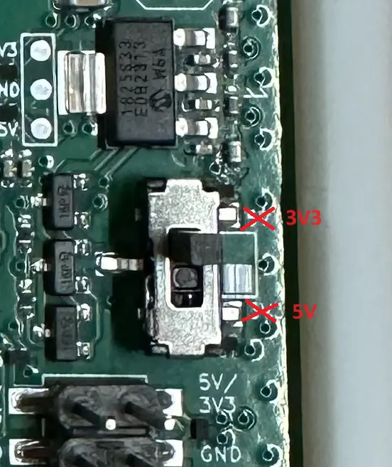
The indication on their boxes is correct:
The Tiny Scarab draws 5V power from its USB-C connector. The 5V power rail is highly protected:
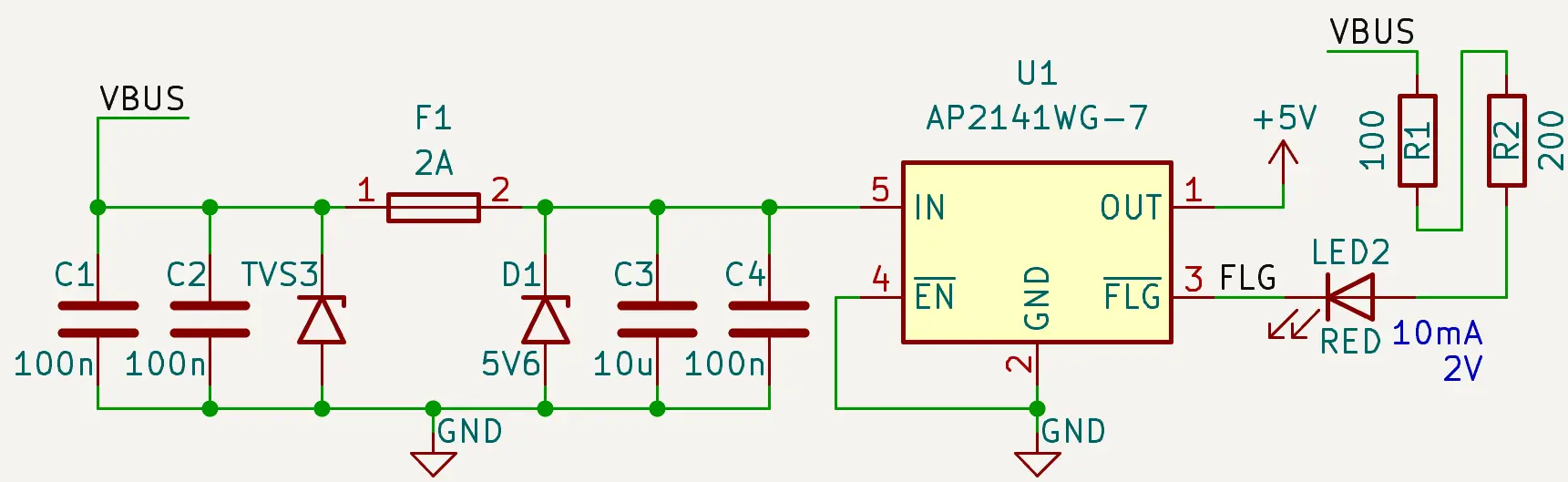
Let's go over all the safety measures.
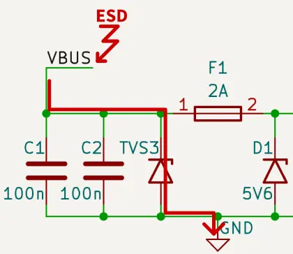
TVS diode TVS3 (SMAJ5.0A) protects the board from incoming voltage transients and ESD discharges on the 5V line:
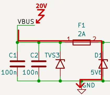
The TVS diode is ideal for short voltage transients - like an ESD discharge. But what about permanent overvoltage incidents? What if a faulty USB-C charger outputs 20V on the VBUS line? In that case, fuse F1 (MFU0603FF02000P500) cooperates with zener diode D1 (1SMA4734A) to protect the board:
Chip U1 (AP2141WG-7) limits the current flow to the whole board at 500mA. This limit ensures that any PC can drive the board risk-free:
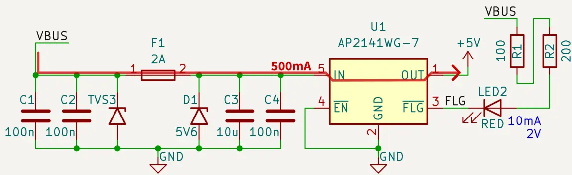
There's already a 2A fuse on the 5V line. Why don't we remove this U1 chip and just reduce the 2A fuse to 500mA?
Fuse F1 and current-limiting chip U1 serve an entirely different purpose. Fuse F1 (in collaboration with zener diode D1) protects the board from permanent overvoltage incidents. Replacing fuse F1 with a 500mA version isn't a good idea because the on-resistance would be too high. Leaving out the fuse and only relying on current-limiting chip U1 isn't smart either - a fuse is just perfect because of its simplicity and robustness. Summarized, the roles of fuse F1 and chip U1 are:
Fuse F1: simple and robust, ideal for the overvoltage incident described earlier.
Chip U1: more sophisticated, will limit current to 500mA while keeping a low on-resistance.
Voltage Conversion content
Voltage Selection content
Flash/Debug Probe: The whole upper part of the board is reserved for the flash/debug probe circuitry. The center of this flash/debug probe is the CH32V305FBP6 MCU. There are roughly three ways to interact with this chip:
The 10-pin connector on the right side of the chip can be used to flash new firmware to the flash/debug probe. You won't have to do that, though. Normally, the probe is in perfect state when you receive the board.
The 4 test pins below the chip - named RST, TX, RX and SWDIO let you eavesdrop on the communication between the CH32V305FBP6 flash/debug probe MCU and the CH32V003F4P6 target MCU. So while you're flashing a new firmware to your target chip, you should "see" signals flowing through these test pins. Also, during a debug session, signals will pass through. When you're not flashing new firmware, nor running a debug session, these test pins should remain silent.
The USB-C connector at the top has its USB-P and USB-N pins directly connected to the CH32V305FBP6 flash/debug probe MCU. In other words - you'll be able to plug the board into your computer and communicate with the flash/debug probe to:
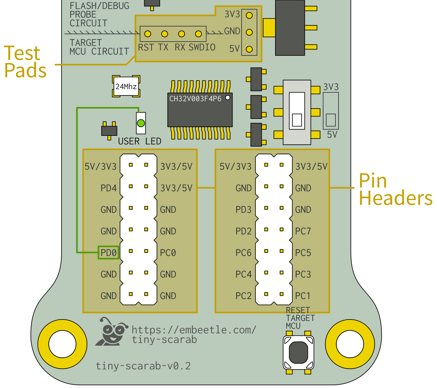
The CH32V003F4P6 target MCU is the heart of the Tiny Scarab board. Almost all its pins are accessible through the Pin Headers at the bottom.
The USER LED is connected to the PD0 pin of the target MCU. Use this LED to test your first blinky project.
Almost all pins of the CH32V003F4P6 target MCU are accessible through these pin headers, with a few exceptions:
PD1 and PD2 (pin 18 and 19) are used to flash code to the target MCU. They are not accessible through the pin headers (but you can access them on the test pads in the middle of the board).
PD5(RX) and PD6(TX) (pin 2 and 3) are routed to the on-board flash/debug probe. They are not accessible through the pin headers (but you can access them on the test pads in the middle of the board).
PA1 and PA2 (pin 2 and 3) are clock pins, routed to the crystal. They are not accessible through the pin headers.
The Tiny Scarab has an on-board flash/debug probe. This means you can connect the board to your computer and start programming without further ado:
After connecting the board to your computer, you should install the WCH-LinkE-r0-1v3 on-board probe:
Attention! Even if you have installed the WCH-LinkE-r0-1v3 probe before, you should check if it is operating in ARM or RISC-V mode. Click the button above for more information.
Follow the steps below to get your board up and running with a blinky LED project.
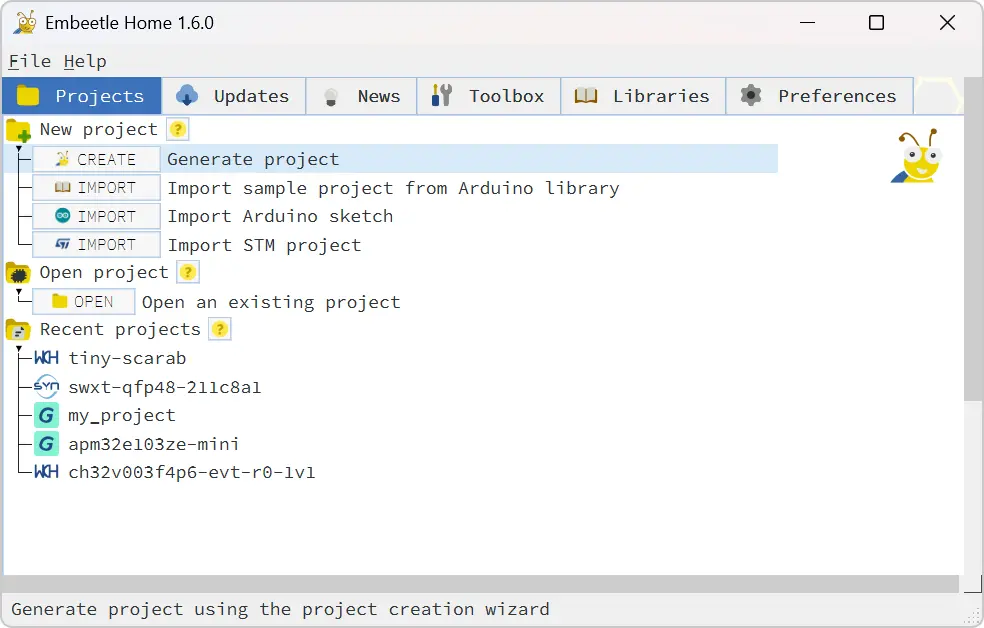
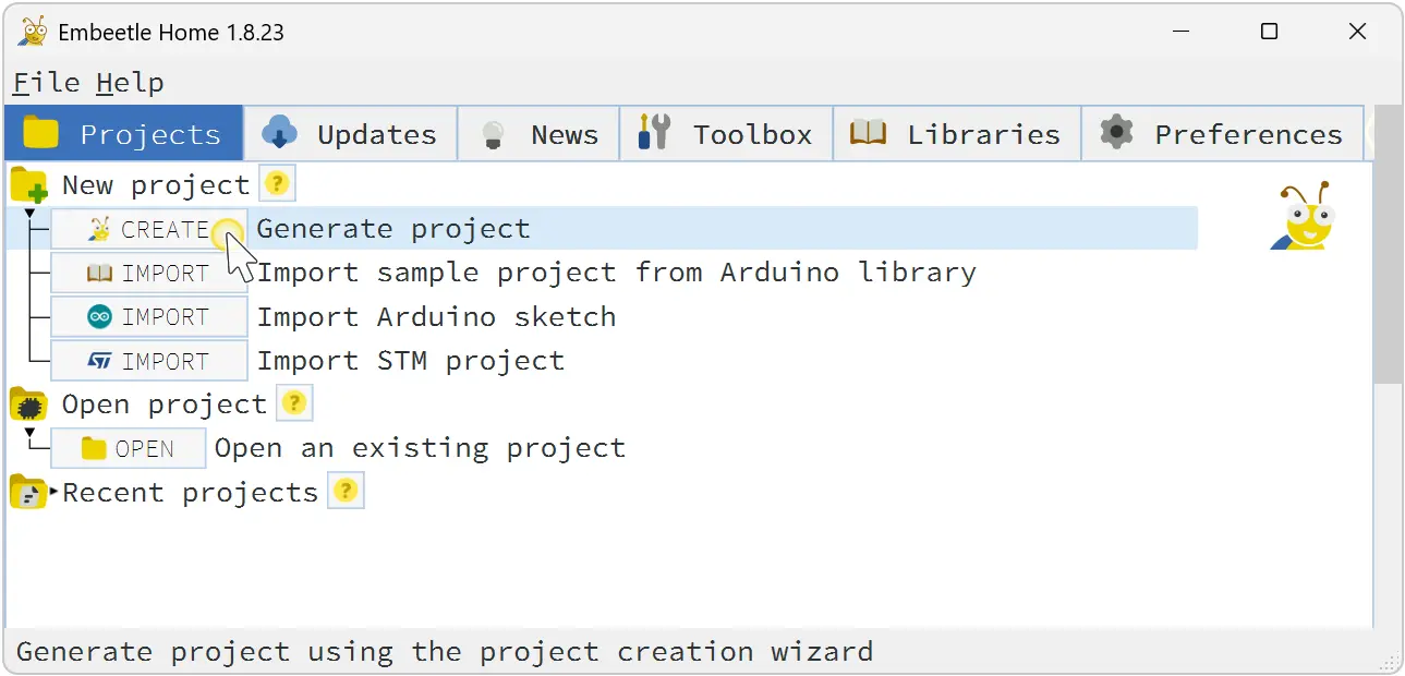
Launch Embeetle IDE (download if you haven't already). Click CREATE PROJECT in the Embeetle Home Window:
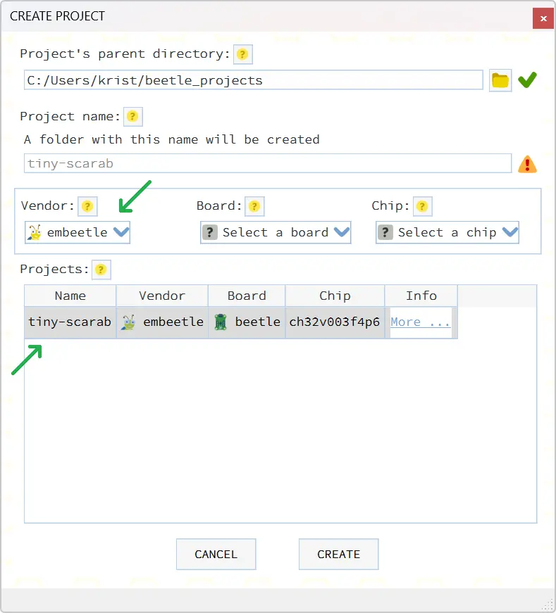
In the CREATE PROJECT window, select the board's vendor embeetle and click on the tiny-scarab project. Then click CREATE:
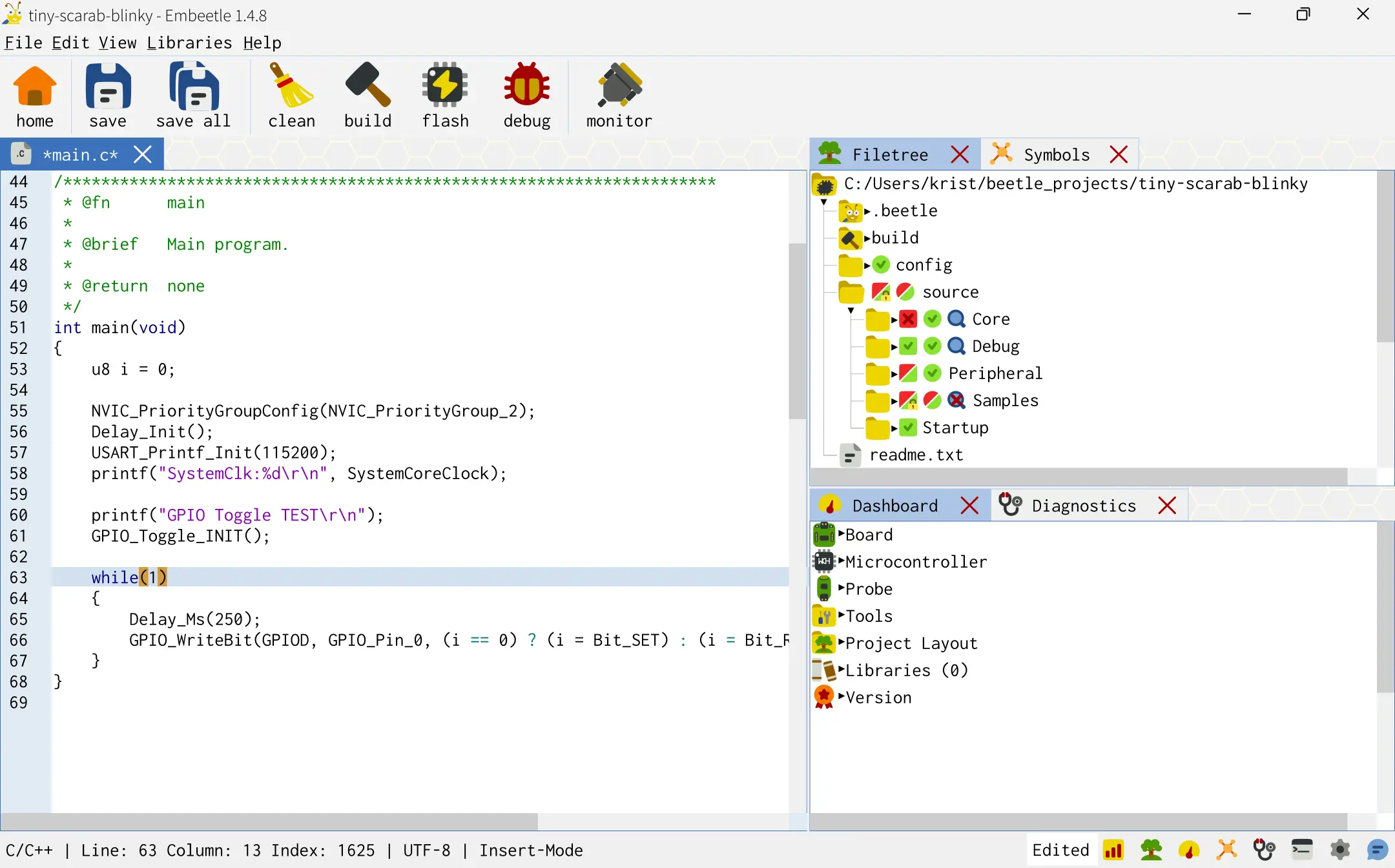
The Tiny Scarab blinky LED project opens:
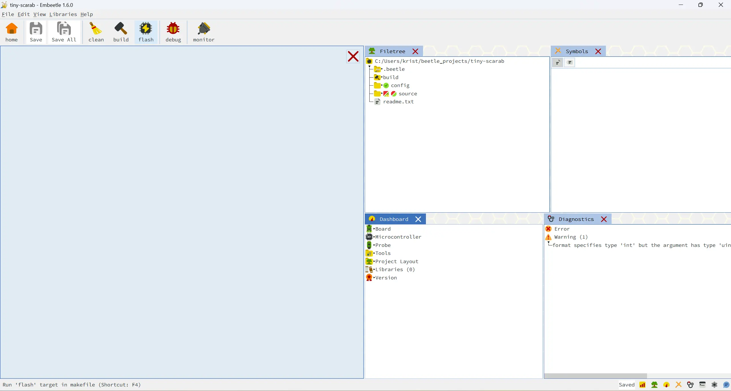
Click the flash ![]() button. Embeetle
builds your code and then flashes it to the MCU. You should see the LED blinking now.
button. Embeetle
builds your code and then flashes it to the MCU. You should see the LED blinking now.
If it fails, check that:
Did you install the WCH-LinkE-r0-1v3 probe correctly? Check out chapter 5.Installation above.
Is your WCH-LinkE-r0-1v3 probe in ARM or RISC-V mode? Check out chapter 5.Installation again.
Check out other common Flash Problems here.
We prepared a baremetal project for the Beetle Board. A baremetal project uses no HAL (Hardware Abstraction Layer) nor RTOS (Real-Time Operating System). You basically access the registers directly.
The baremetal project for the Beetle Board only uses three code files: a startup assembly file, a header file that defines the register addresses, and main.c. You can read all about it in this blog post:
To open the baremetal project in Embeetle, follow these steps:
Launch Embeetle and click the CREATE button:
Select WCH for the Vendor and ch32v00x for the board. Then choose the sample project ch32v003f4p6-evt-r0-1v1-baremetal:
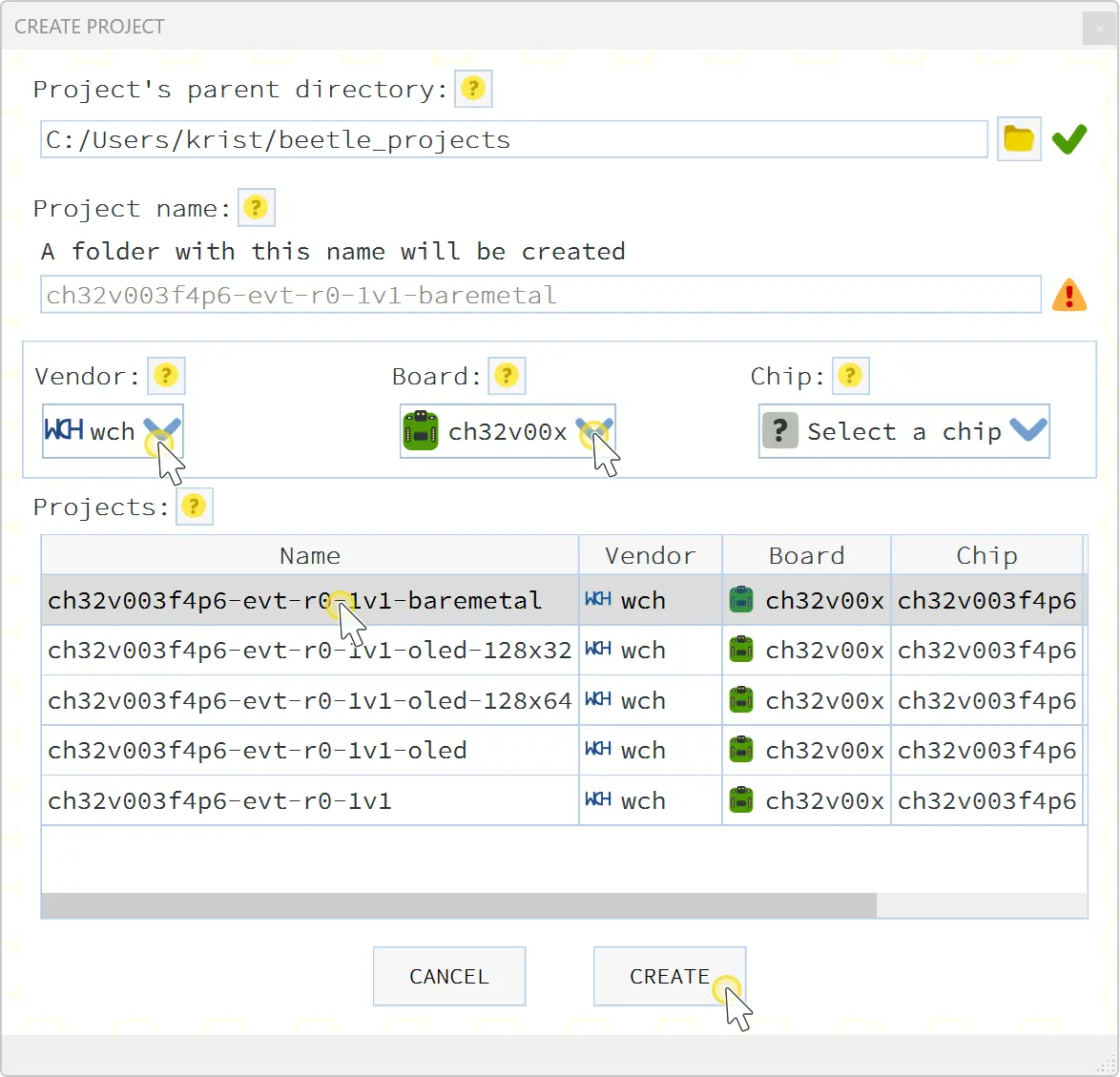
Click CREATE. Embeetle downloads the sample project from the server. Then Embeetle checks if you already have the right tools on your PC. If not, Embeetle offers to download them:
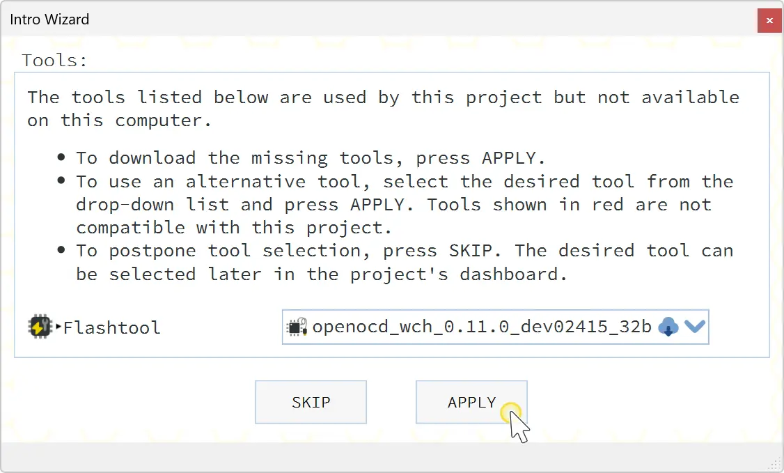
Click APPLY. The tools are downloaded and the project opens:
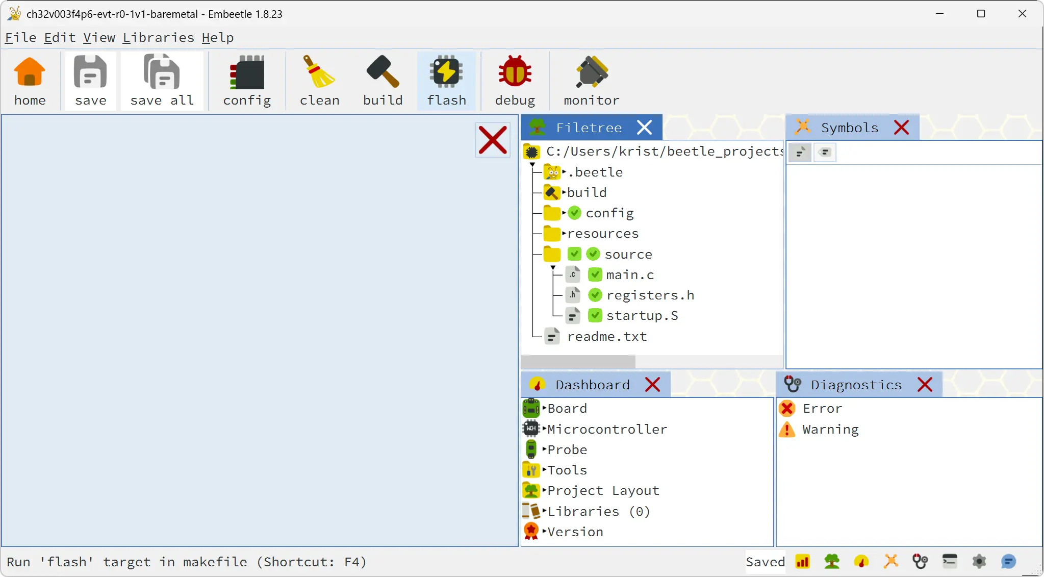
Click the flash ![]() button. Embeetle
builds your code and then flashes it to the MCU. You should see the LED blinking now.
button. Embeetle
builds your code and then flashes it to the MCU. You should see the LED blinking now.
If it fails, check that:
Did you install the WCH-LinkE-r0-1v3 probe correctly? Check out chapter 5.Installation above.
Is your WCH-LinkE-r0-1v3 probe in ARM or RISC-V mode? Check out chapter 5.Installation again.
Check out other common Flash Problems here.
To understand how this baremetal project works, read the blog post.
When you browse through the WCH sample project in the Filetree, you'll notice that - next to the GPIO project - it contains several deactivated ones:
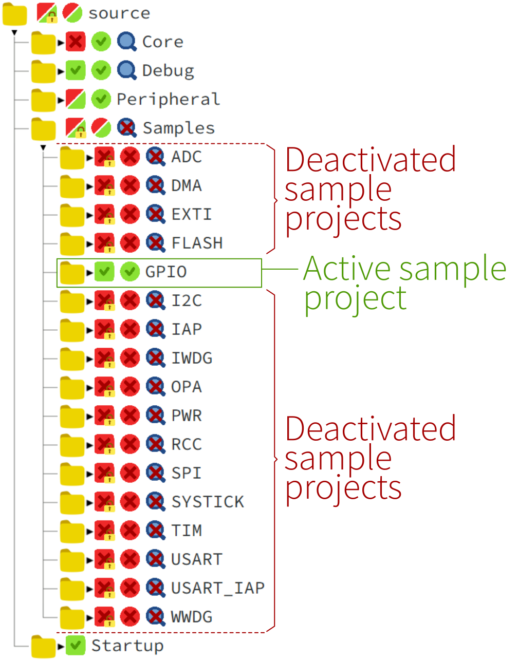
It is very easy to activate another. Keep in mind you can only activate one at a time! The following steps are involved:
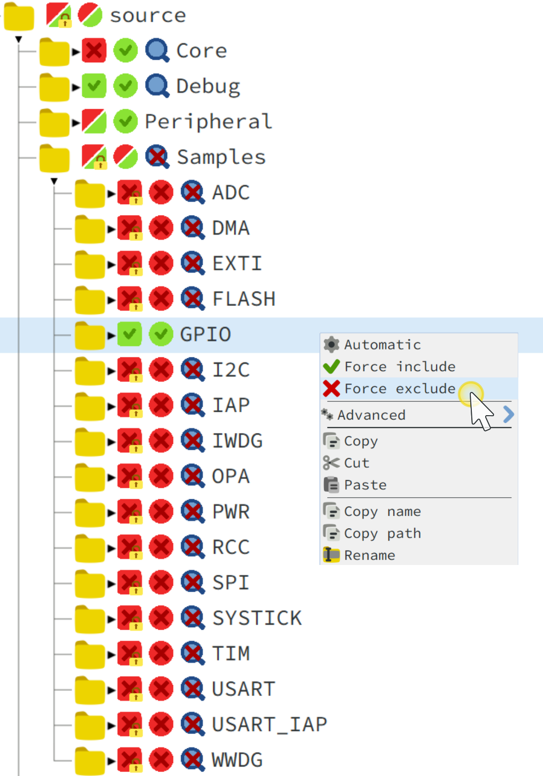
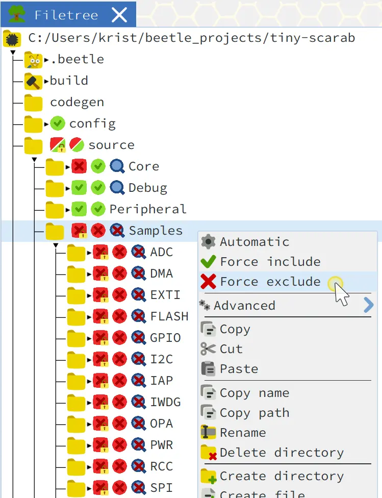
First, deactivate the project that's currently active. Right click on the GPIO folder (at source/Samples/GPIO) and select Force exclude in the context menu:
Now wait a bit for the Source Analyzer to complete its analysis, indicated by the green progressbar in the right-bottom corner.
Next, navigate to the sample project you want to activate. Be careful! It's not always clear how deep you have to navigate into the source/Samples/ folder to reach a project! Sometimes the project is right under source/Samples/, such as source/Samples/GPIO. In other cases, you'll have to dig quite deep, like source/Samples/ADC/ADC_DMA:
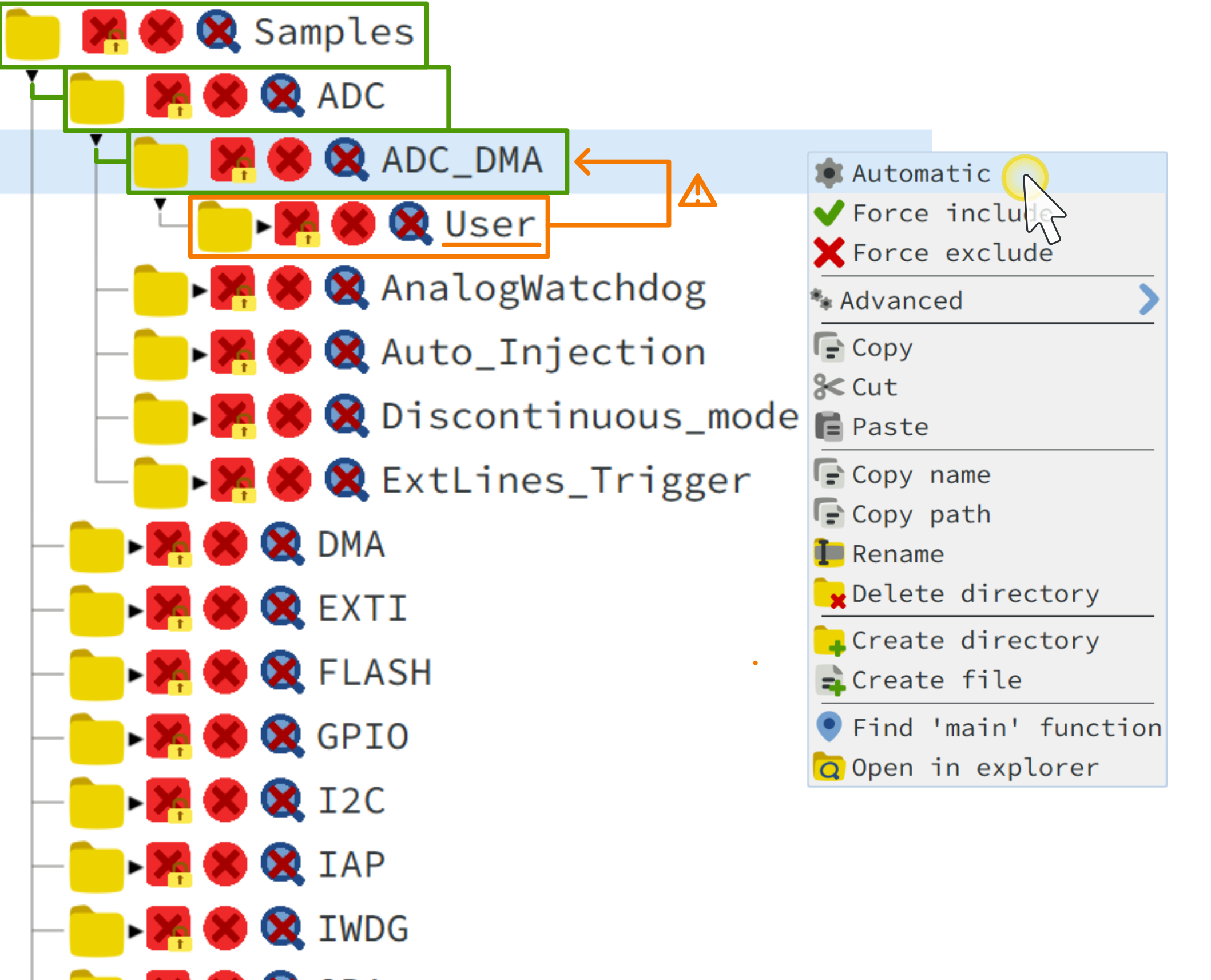
The trick is to look for a User subfolder. The moment you encounter this subfolder, you know that the parent folder represents a sample project.
Now right-click on the project folder and select Automatic in the context menu (see figure above). The 'Automatic' option lets Embeetle know it should search in this folder for source files that can be added to the build. Alternatively, you can select Force include, which is more aggressive: all source files will be added to the build - required or not. This option is usually not needed.
Usually steps 1 and 2 are sufficient. However, for some sample projects, you need to do a little extra effort. You could encounter a few undefined globals when activating a project in the Diagnostics tab:
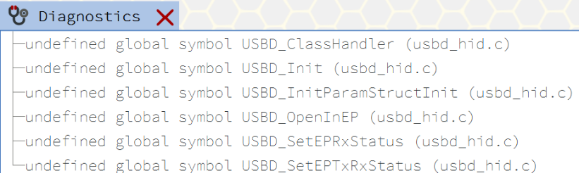
Embeetle reports missing symbols when it doesn't have access to all the required source files to build the project properly. In that case, you'll have to navigate through the Filetree and activate the source files that are needed for the project.
In other cases, you'll need to modify the symbols passed to the project from the makefile. Open the file <project>/config/dashboard.mk and modify the variable TARGET_COMMONFLAGS:
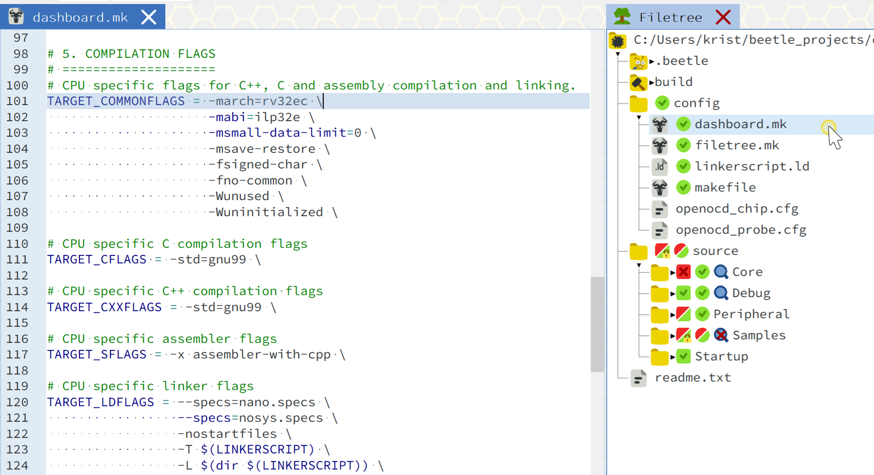
Modifying the TARGET_COMMONFLAGS variable is luckily not needed for most WCH sample projects.
Embeetle intends to simplify the switch between sample projects in the WCH SDK even further. A simple dropdown menu in the Dashboard will let you select one of the available samples, after which Embeetle activates automatically all the relevant folders and modifies the symbols in <project>/config/dashboard.mk automatically. No more need to go hunting for "missing symbols".
Recently, Embeetle inegrated a new feature: the grahical Pin, Clock and Peripheral Config Tool. This tool allows you to configure your MCU's pins, clock and peripherals. It's an experimental feature, only available for a few select MCUs right now - the CH32V003F4P6 being one of them.
The code that the PinConfig Tool generates is a sample project in its own right. Therefore, you first you need to deactivate all other sample projects:
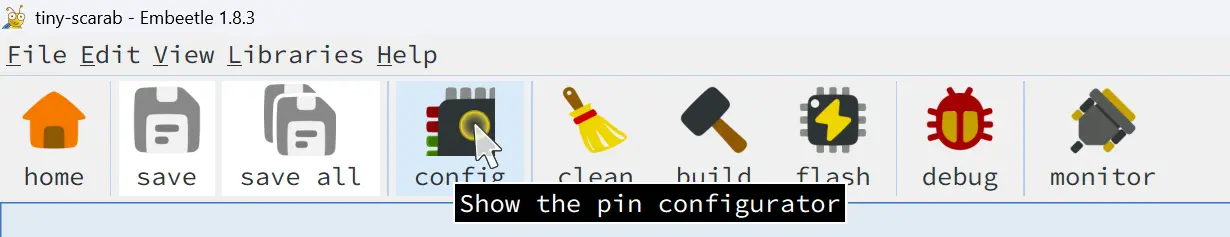
Now launch the PinConfig Tool:
The tool has three tabs. Let's go through them one by one.
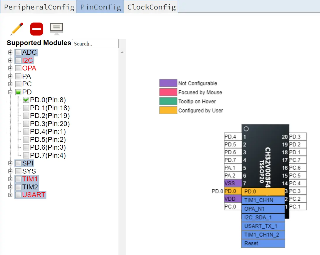
In the PinConfig tab, you can select the functionalities for each pin. The LED on the board is connected to pin PD0, so let's make that one a GPIO output:
In the Peripheral tab, you can configure the peripherals. The only peripheral available so far for the CH32V003F4P6 is the GPIO (more are coming in the following weeks). Make sure this peripheral is enabled properly:
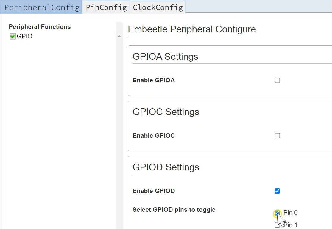
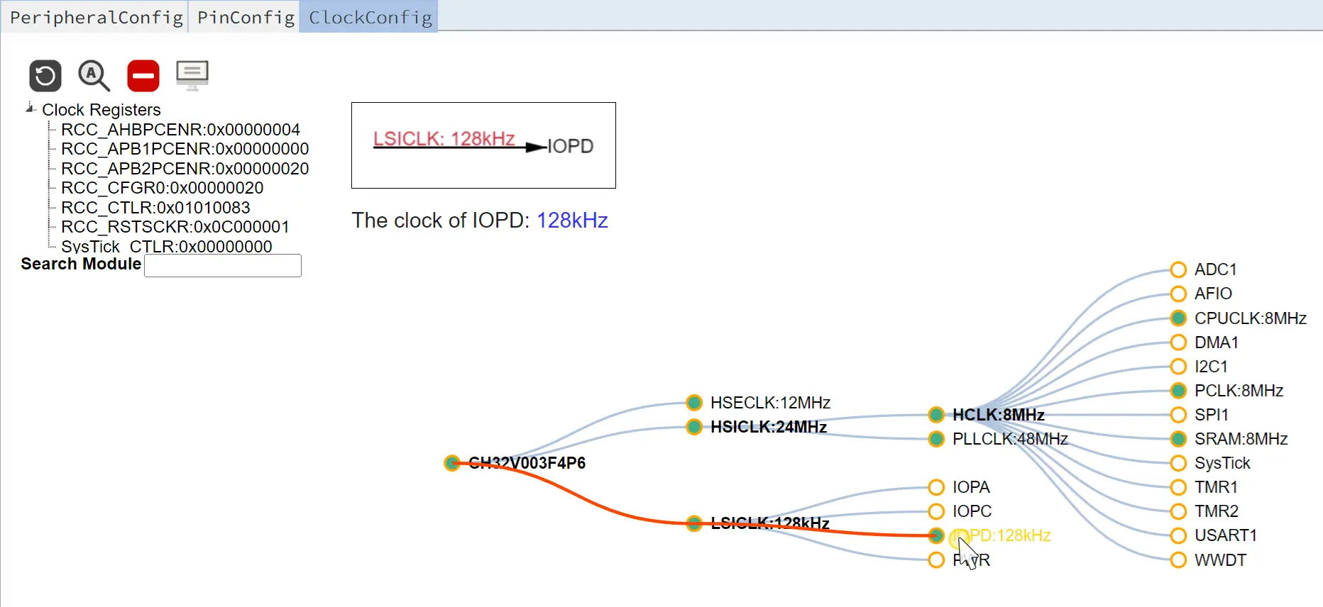
Last but not least - check the Clock tab. Make sure that the clock for port D is enabled:
When you're done configuring the pins, peripherals and clocks, click the Generate Code button. The PinConfig Tool generates a sample project in the Filetree, in the <project>/codegen folder:
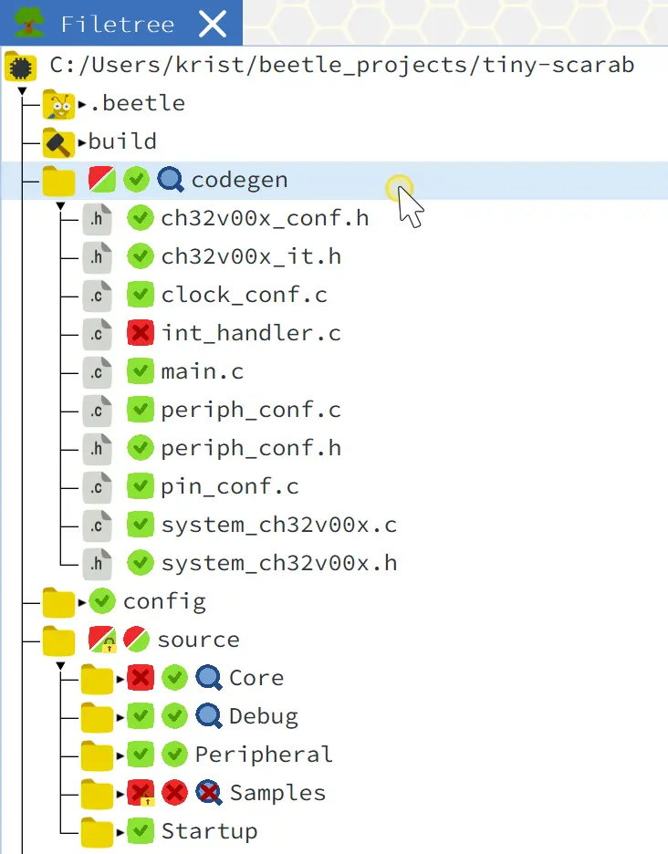
Congrats! You've just created a sample project with the PinConfig Tool. Now you can build and flash it to your board.
Programming tutorial:
Microcontroller references:
Board references: